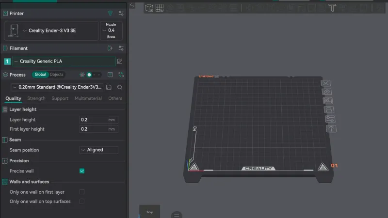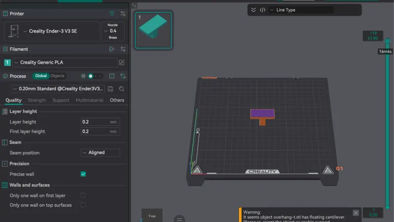
The OrcaSlicer interface is built around five tabs along the top: Home, Prepare, Preview, Device and Project. This tour covers each tab, the left settings panel, the toolbar and the Preview readout in OrcaSlicer 2.4.2 on macOS. Every button name below was checked in the running program.
What are the five tabs in OrcaSlicer?
The tabs are Home, Prepare, Preview, Device and Project, and the order is roughly the order you use them. A fresh start looks like this:
- Home shows New Project and Open Project buttons, a Recently opened list and the Orca Cloud Account panel with Login / Register.
- Prepare is where you load a model, choose settings and press Slice plate.
- Preview shows the sliced result layer by layer, with estimates.
- Device is for monitoring a networked printer. With no printer connection set up it simply says "Please set up your printer connection to view the device."
- Project holds project information. Before you fill anything in it reads "No model information" with an Edit Project Info button.
If you have not run the first-launch wizard yet, do that first: see the OrcaSlicer setup wizard walkthrough.
What is in the left panel on the Prepare tab?
The left panel has three stacked sections: Printer, Filament and Process. Each header has small icons, and hovering one shows a tooltip.
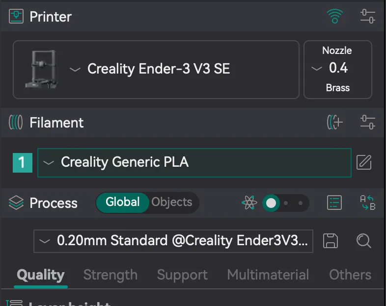
- Printer shows the printer name and a nozzle box (0.4, Brass for our profile). The wifi-style icon is Connection, for linking a networked printer.
- Filament lists each filament slot with a numbered tile and a preset such as Creality Generic PLA. The icons beside the header are Add one filament and Set filaments to use, and the pencil beside the preset is Click to edit preset.
- Process holds the slicing settings. A Global and Objects switch decides whether you are editing settings for the whole plate or for individual objects. The preset drop-down below it names the quality preset, here 0.20mm Standard for the Ender-3 V3 SE, with a save icon and a search icon next to it.
The row of icons above the preset has four items: Cycle settings visibility, a slider labelled Simple settings, View all object's settings and Compare presets. The slider is how you move between the four option modes, which hide or reveal settings. Our profile opened in Simple, which is why the tabs under Process read only Quality, Strength, Support, Multimaterial and Others. The beginner guide explains why to stay in Simple mode at first.
What does each toolbar button do?
The toolbar runs across the top of the build plate. Many buttons are greyed out until you load and select a model, and each shows its name and shortcut when you hover over it. These are the ones we hovered over, in order from the left:

| Button | Shortcut shown | What it does |
|---|---|---|
| Add | Cmd+I on macOS | Import a model file |
| Add plate | none | Add another build plate to the project |
| Auto orient | Q (Shift+Q for all objects on the plate) | Turn the selected objects into a better print orientation |
| Arrange | A (Shift+A for selected plates) | Lay objects out on the plate |
| Add instance / Remove instance | + and - | Copy or remove copies of the selected object |
| Split to objects / Split to parts | none | Break a combined model into separate pieces |
| Variable layer height | none | Change layer height along the model |
| Move, Rotate, Scale | M, R, S | Transform the selected object |
| Lay on Face | F | Put a chosen face flat on the bed |
| Mesh Boolean | B | Combine meshes |
| Support Painting | L | Paint where supports go |
| Seam painting | P | Paint where layer seams go |
| Paint-on fuzzy skin | H | Paint a rough texture on a surface |
| Emboss | T | Add text or shapes |
| Measure | U | Measure features on a model |
| Assemble | Y | Needs at least two volumes selected |
| Brim Ears | E | Add brim only at chosen points |
| Assembly View | none | Switch to the assembly view |
The shortcut and name columns come straight from the tooltips; the "what it does" column is a plain-language summary. Later lessons use Arrange, Move, Rotate, Scale and Support Painting in practice, and the walkthrough on choosing between slicers shows how these tools compare with other programs.
When you select a model, an information box appears at the bottom right of the Prepare view showing the object name, size, volume and triangle count. For our T-shaped test model it read 40 x 20 x 24 mm and 5200 mm³.
How do you read the Preview tab?
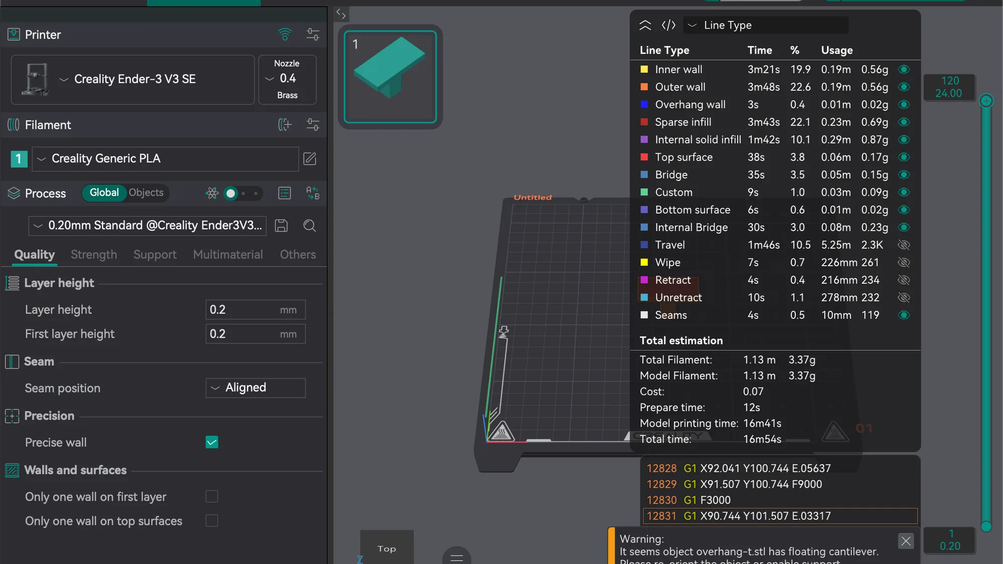
Press Slice plate at the top right, then open the Preview tab. The panel on the right is a table of line types, listing each one's print time, share of the total and filament use: walls, sparse infill, top surface, bridge and so on, plus travel moves. Beneath it is a Total estimation block with total filament in metres and grams, cost, prepare time, model printing time and total time. Everything there is the slicer's estimate, not something measured on a printer.
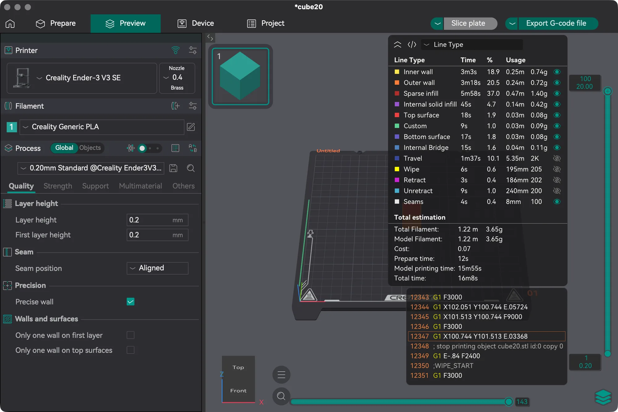
A vertical slider on the right of the view moves through the layers, with a horizontal slider along the bottom for moves within a layer. In our T-shaped model it ran from layer 1 at 0.20 mm to layer 120 at 24.00 mm. A small G-code panel shows the commands for the current move.
Preview also shows warnings. For the T-shaped model it displayed: "It seems object overhang-t.stl has floating cantilever. Please re-orient the object or enable support generation." That is your cue to look at supports, which the supports lesson in this course covers.
Next lesson: Orca Slicer Import Model: Move, Scale, Rotate, Arrange.