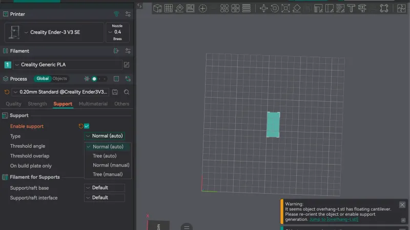
Cura supports are switched on with one toggle, and this lesson shows what that toggle does, how Normal and Tree supports differ and how to stop supports forming where you do not want them. We tested it in UltiMaker Cura 5.13.0 on macOS with the overhang-t test part, a T shape that hangs a top bar over empty air.
How do you turn on supports in Cura?
Open the print settings bar at the top right of the Prepare stage. If it only highlights, click it again. In Recommended mode, covered in the Recommended settings lesson, scroll to the row called Support and click its switch. It was off at the start, and the bar at the top right showed Support as Off until we flipped it.
Two drop-downs appear under the switch. Support Structure offers Normal and Tree. Placement offers Touching Buildplate and Everywhere. After we switched the toggle on, the first values we saw were Normal and Everywhere. If you want a refresher on why overhangs need support at all, read supports explained.
What is the difference between Normal and Tree supports?
Switch to Custom mode, search for support structure and hover the label. The tooltip says that Normal support creates a structure directly below the overhanging parts and drops those areas straight down. Tree support creates branches towards the overhanging areas, so that the model is supported on the tips of those branches, and the branches can crawl around the model to support it from the build plate as much as possible. Under Affects it lists Support Wall Line Count, Support Density, Support Horizontal Expansion and Minimum Support Area.
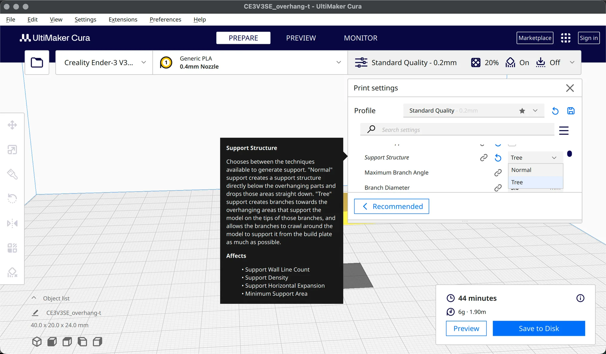
In practice, Normal gives a solid column under each overhang and Tree gives thin branches with small tips. On our test part Preview showed four trunks with branches fanning out under the top bar, and the red shell of the stem standing between them. Tree touches the model at the tips only, which leaves less to clean off. We did not print anything, so we cannot say how either one peels off.
What does Placement change?
Touching Buildplate only builds supports that start on the bed. Everywhere also lets them rest on the model. Our overhang-t part has nothing under the bar except air and the stem, so both choices gave the same estimate. A part with a ledge halfway up would show a difference, but we did not test one. We only used overhang-t for the estimates below and did not slice bridge.stl for this lesson.
Which settings are in the Support category in Custom mode?
Click Show Custom, then open the Support category. The list is long, and we did not record which setting visibility level was active, so yours may show fewer rows. With Normal selected we read these values on our Standard Quality 0.2 mm profile:
- Generate Support: a tick box, ticked.
- Support Structure: Normal.
- Support Placement: Everywhere.
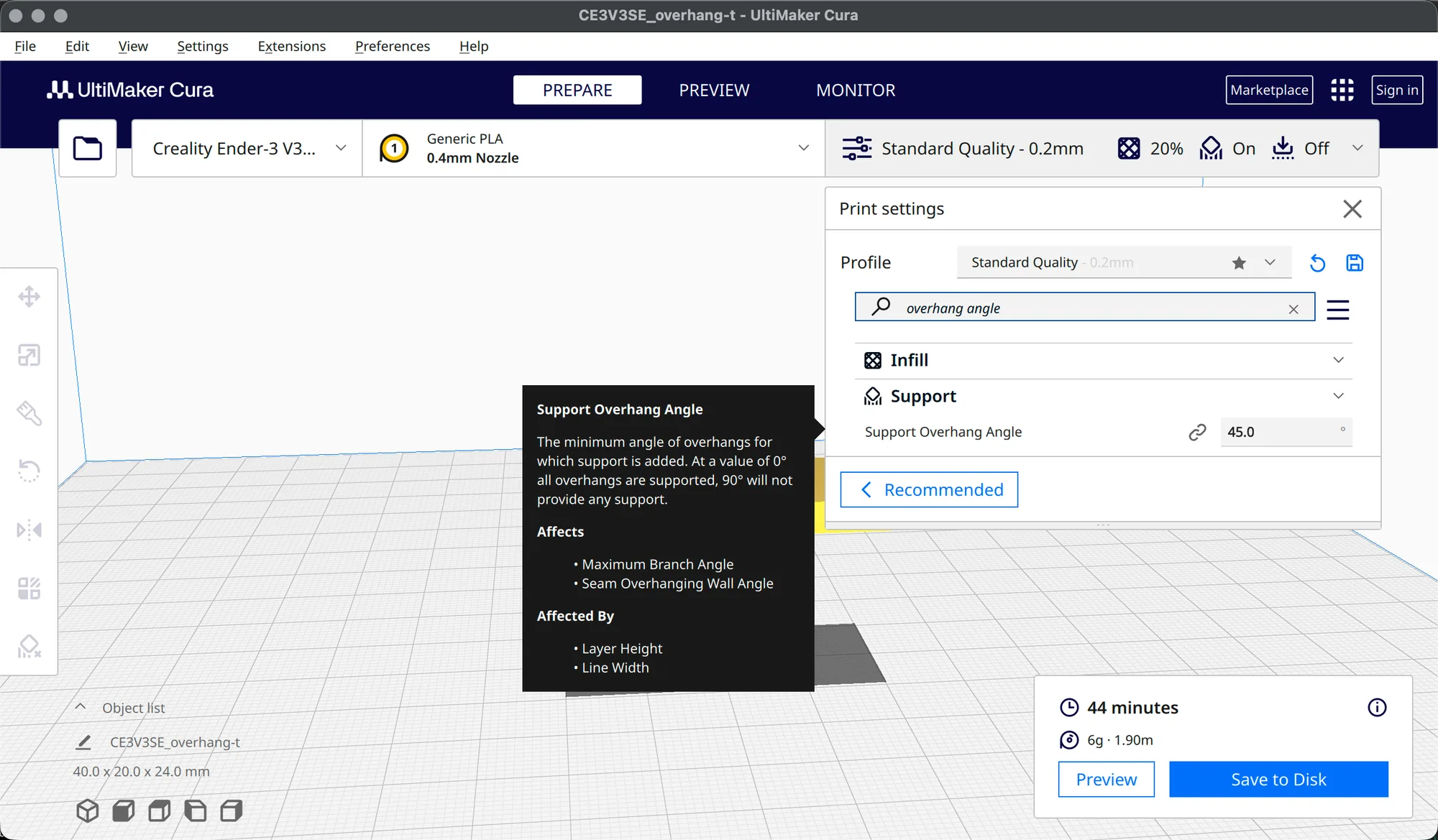
- Support Overhang Angle: 45.0 degrees.
- Support Pattern: Zig Zag.
- Support Wall Line Count: 0, with Support Interface, Roof and Bottom Wall Line Count also 0.
- Connect Support ZigZags: ticked.
- Support Density: 20.0 percent, which gives a Support Line Distance of 2.0 mm.
- Enable Support Brim: ticked, with Support Brim Width 4.0 mm and Support Brim Line Count 10.
- Support Z Distance: 0.2 mm, with Support Top Distance and Support Bottom Distance both 0.2 mm.
- Support X/Y Distance: 0.8 mm, and Support Distance Priority: X/Y overrides Z.
- Support Z Seam Away from Model: ticked, with Min Z Seam Distance from Model 0.8 mm.
The Support Overhang Angle tooltip reads: "The minimum angle of overhangs for which support is added. At a value of 0 degrees all overhangs are supported, 90 degrees will not provide any support." It lists Maximum Branch Angle and Seam Overhanging Wall Angle under Affects, and Layer Height and Line Width under Affected By. A bigger angle means fewer supports, and at the 45 degree default steeper faces are left alone.
Switch Support Structure to Tree and the list changes. We saw Maximum Branch Angle 45.0, Branch Diameter 5.0 mm, Trunk Diameter 25.0 mm, Branch Diameter Angle 7.0, Preferred Branch Angle 30.0, Diameter Increase To Model 1.0 mm, Minimum Height To Model 3.0 mm, Initial Layer Diameter 7.5 mm, Branch Density 30.0 percent, Tip Diameter 0.8 mm, Limit Branch Reach ticked and Optimal Branch Range 30.0 mm. Support Wall Line Count became 1, and Support Density showed 0.0 with a pale field, so the density rows do not appear to be used for tree supports. We did not confirm that, so treat it as an observation.
How do you see supports in Preview?
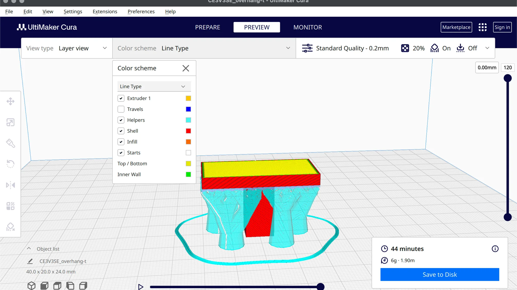
Slice, then click Preview. With the Line Type colour scheme, a legend lists Extruder 1, Travels, Helpers, Shell, Infill, Starts, Top / Bottom and Inner Wall. Supports belong to Helpers, shown in pale cyan. Shell is red, Top / Bottom is yellow and Inner Wall is green. Travels, in blue, was unticked. Our Tree preview also showed a thin cyan ring on the plate around the part, which we think is the support brim since Enable Support Brim was ticked, though we did not confirm it. Adhesion itself was Off.
For help with layers and the other view types, the preview lesson later in this course goes through them. See also brim vs raft vs skirt for the adhesion side.
How much do supports change the slicer estimate?
We sliced overhang-t with Standard Quality 0.2 mm, 20% Cubic infill and Adhesion off, changing only the support options. These are slicer figures, not print results.
| Support setup | Slicer time | Material |
|---|---|---|
| Off | 29 minutes | 4 g, 1.18 m |
| Normal, Touching Buildplate | 45 minutes | 9 g, 2.94 m |
| Normal, Everywhere | 45 minutes | 9 g, 2.94 m |
| Tree, Touching Buildplate | 44 minutes | 6 g, 1.90 m |
| Tree, Everywhere | 44 minutes | 6 g, 1.90 m |
Supports added 15 or 16 minutes here. Tree needed about a third less filament than Normal, which is the usual reason to pick it, though the time saving was one minute. Placement made no difference on this shape. Compare this with the Orca Slicer supports lesson if you use both programs.
What does the Support Blocker do?
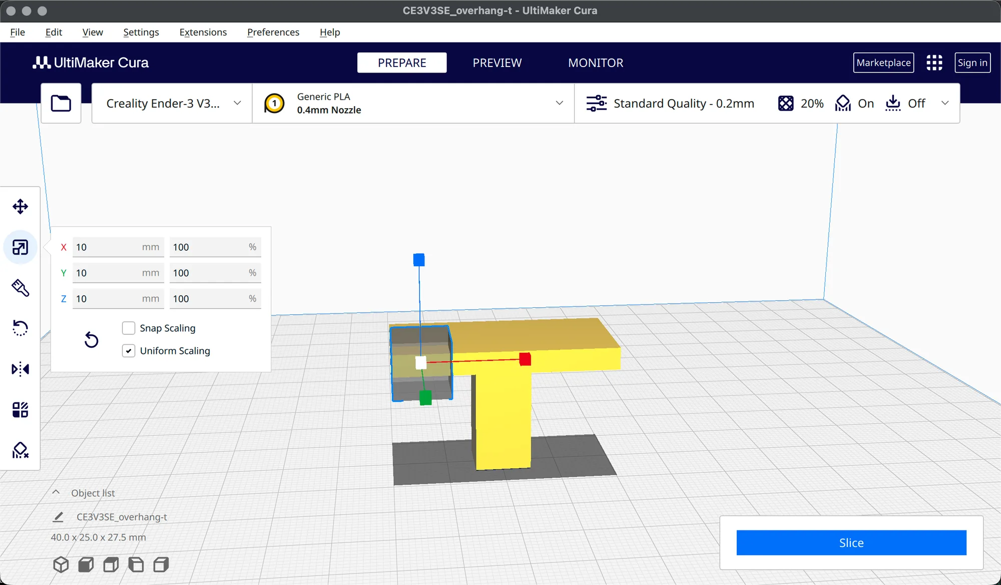
The last icon in the left toolbar is Support Blocker, with the shortcut E in its tooltip. Click the icon, then click on the model. A translucent box appeared at the point where we clicked, on the left end of the T bar. Our first click on the toolbar icon only showed the tooltip, so click twice if nothing happens. Pressing E on the keyboard did nothing in our test.
The blocker is a separate object. Select it and open the Scale tool, and it showed 10 mm on X, Y and Z at 100%, with Uniform Scaling ticked. The object size readout at the bottom left changed from 40.0 x 20.0 x 24.0 mm to 40.0 x 25.0 x 27.5 mm while the blocker was in place. Any support that would fall inside the box is left out. With Normal and Everywhere, the estimate stayed at 45 minutes and the filament dropped from 2.94 m to 2.89 m, so the small box removed only a little support.
To remove it, select the blocker and use Edit, Delete Selected. The Delete key did nothing for us. We then switched Support off, which returned the estimate to 29 minutes, and left Cura in Recommended mode. The next lesson is Cura adhesion (cura-adhesion), which is not published yet.
Next lesson: Cura Brim and Adhesion Settings: Skirt, Brim, Raft.