Orca Slicer variable layer height lets one model use thin layers where it curves gently and thick layers where it is steep. This lesson, tested in OrcaSlicer 2.4.2 on macOS, opens the tool, presses Adaptive on a dome and compares the slicer estimate before and after. We only sliced and read numbers. We did not print anything.
What is variable layer height in OrcaSlicer?
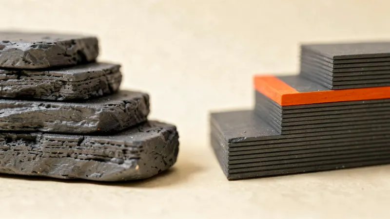
Normally a process preset such as 0.20mm Standard gives every layer the same height. For the background, see our guide layer height explained. Variable layer height keeps the preset as the starting point but lets you give different heights to different parts of one object.
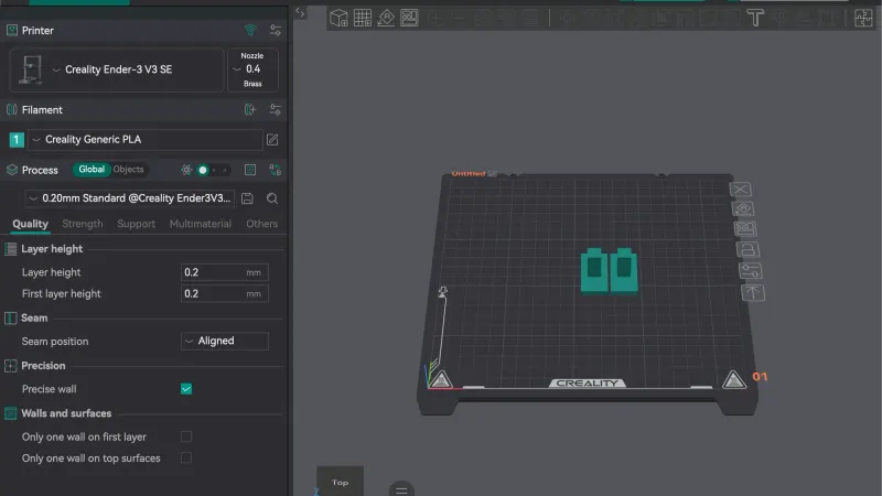
We used the setup from our previous lesson on saving and exporting: Simple mode, Creality Ender-3 V3 SE, Creality Generic PLA and 0.20mm Standard. Our usual overhang test part is a poor demo here because it has only flat faces, so we made a simple dome as an STL file (a 4 mm base with a hemisphere on top) and imported it with Cmd+I. OrcaSlicer reported it as dome.stl, size 40 x 40 x 24 mm, volume 21742.3 mm3, 6272 triangles. A dome suits the tool because its top is nearly flat while its sides are steeper.
How do you open the Variable layer height tool?
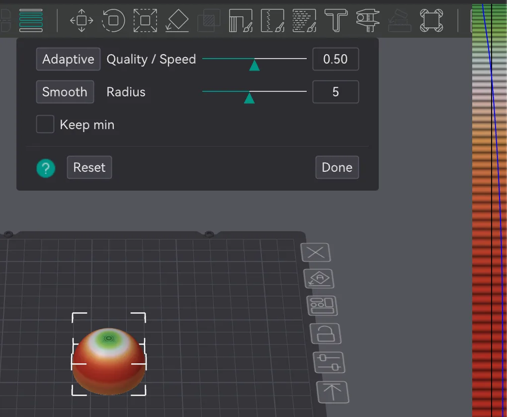
Click the Prepare tab and select the object. In the toolbar at the top of the 3D view, hovering the icon made of four stacked horizontal lines showed the tooltip Variable layer height. It sits to the right of the arrange and plate icons. We clicked it.
The rest of the toolbar greyed out and a panel opened below it. We read these controls:
- Adaptive button, next to a slider named Quality / Speed with a box that read 0.50
- Smooth button, next to a slider named Radius with a box that read 5
- A checkbox named Keep min, unticked
- A round ? button, a Reset button and a Done button
Before we pressed anything, the dome turned plain grey and Reset was greyed out. A coloured strip with a thin line down it appeared along the right edge of the 3D view. That strip is the layer height profile. In our window it was partly cut off at the screen edge, so we could only see its left part. We did not get the question mark help text to appear, so we do not describe it. We also did not test what the Keep min checkbox changes.
What do Adaptive and Smooth do?
We pressed Adaptive with Quality / Speed at 0.50. The dome recoloured at once: red on the steep sides, with a green and white ring toward the top. The profile strip at the right filled with bands of colour, from red through orange and yellow near the middle to green near the top, and a blue line traced the height values down the strip. The Reset button became active.
Then we pressed Smooth with Radius at 5. The colour changes looked more gradual afterwards. We did not move either slider, so we cannot say how the other values behave. The only values we tested were 0.50 and 5, the defaults. Then we pressed Done, which closed the panel and returned the normal toolbar.
How does variable layer height change the slicer estimate?
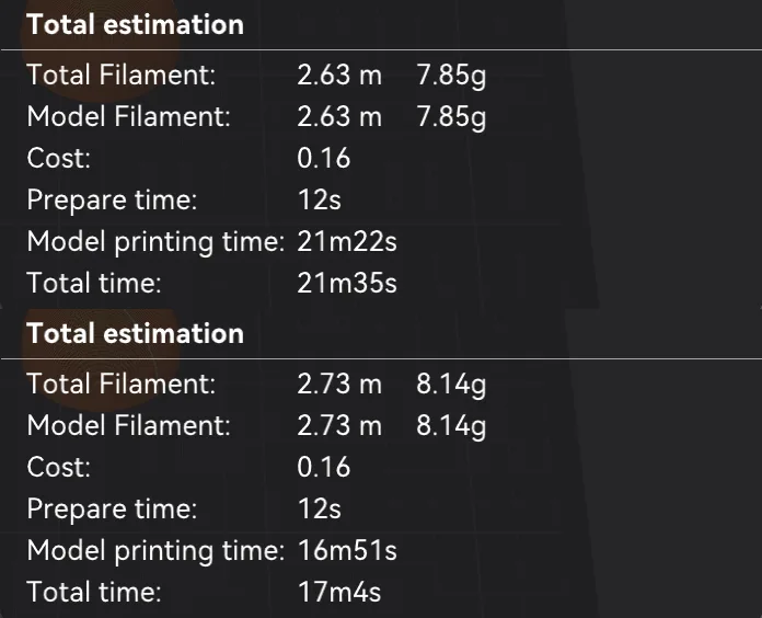
We sliced the dome twice with the same preset, once with the fixed 0.20 mm layers and once after Adaptive and Smooth. The numbers below come from the Total estimation block in Preview, which is the slicer's own estimate.
| Slicer estimate | Fixed 0.20 mm | Adaptive then Smooth |
|---|---|---|
| Layers (upper slider label) | 120 | 93 |
| Top of model (upper slider label) | 24.00 mm | 24.04 mm |
| Model printing time | 21m22s | 16m51s |
| Total time | 21m35s | 17m4s |
| Total filament | 2.63 m, 7.85 g | 2.73 m, 8.14 g |
| Cost | 0.16 | 0.16 |
Layers dropped from 120 to 93 and the estimated total time fell by about 4 minutes 31 seconds, roughly a fifth. The filament estimate went up slightly, which surprised us. We did not investigate why, so we will not guess. The top of the model read 24.04 mm instead of exactly 24.00 mm, so the last layer overshoots a little. This is one small shape with the default sliders, so do not treat these figures as typical.
How do you check the result in Preview?
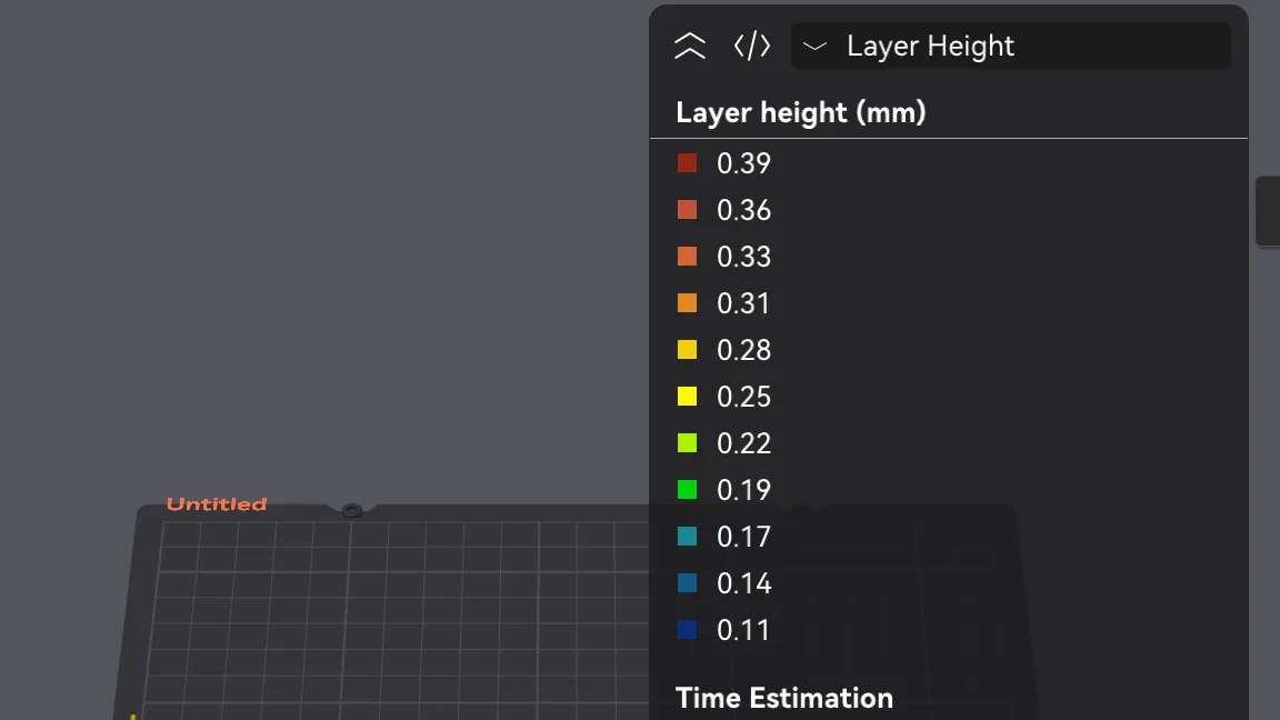
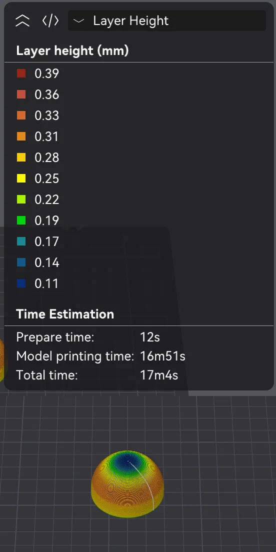
After slicing, we opened the View type drop-down at the top of the Preview legend and chose Layer Height (it is the eighth entry; see our lesson on Preview if you need the list). The legend is titled Layer height (mm) and runs in 11 steps from 0.39 at the red top to 0.11 at the dark blue bottom: 0.39, 0.36, 0.33, 0.31, 0.28, 0.25, 0.22, 0.19, 0.17, 0.14, 0.11.
On the dome, the flat top was dark blue and green, toward the thin end. The steep sides were orange and yellow, toward the thick end. That matches how a slicer thinks: thin layers where a flat or shallow surface would show steps, thicker layers on near vertical walls. The fixed slice would show a single colour for 0.20 mm, as we saw in the previous lesson. We read colours against the legend and did not measure individual layers, so treat the exact heights as approximate.
A practical reminder: the tool stores the profile on the object, so another object on the plate keeps the fixed height. When we were finished, we reopened the tool and pressed Reset, which returned the dome to plain grey, then Done. If your results look unexpected, check the Layer Height view first. Our guide to print speed vs quality explains why time and quality pull in opposite directions. The next lesson, orca-slicer-per-object-settings, covers giving one object its own settings.
Next lesson: Orca Slicer Per Object Settings and Modifiers.