The Strength tab holds the OrcaSlicer infill settings and the wall and shell settings that decide how solid a model is inside. This lesson, tested in OrcaSlicer 2.4.2 on macOS, opens the tab, reads each field's tooltip, lists the infill patterns, and compares slicer estimates for five combinations on one plate.
Where is the Strength tab and which fields does it show?
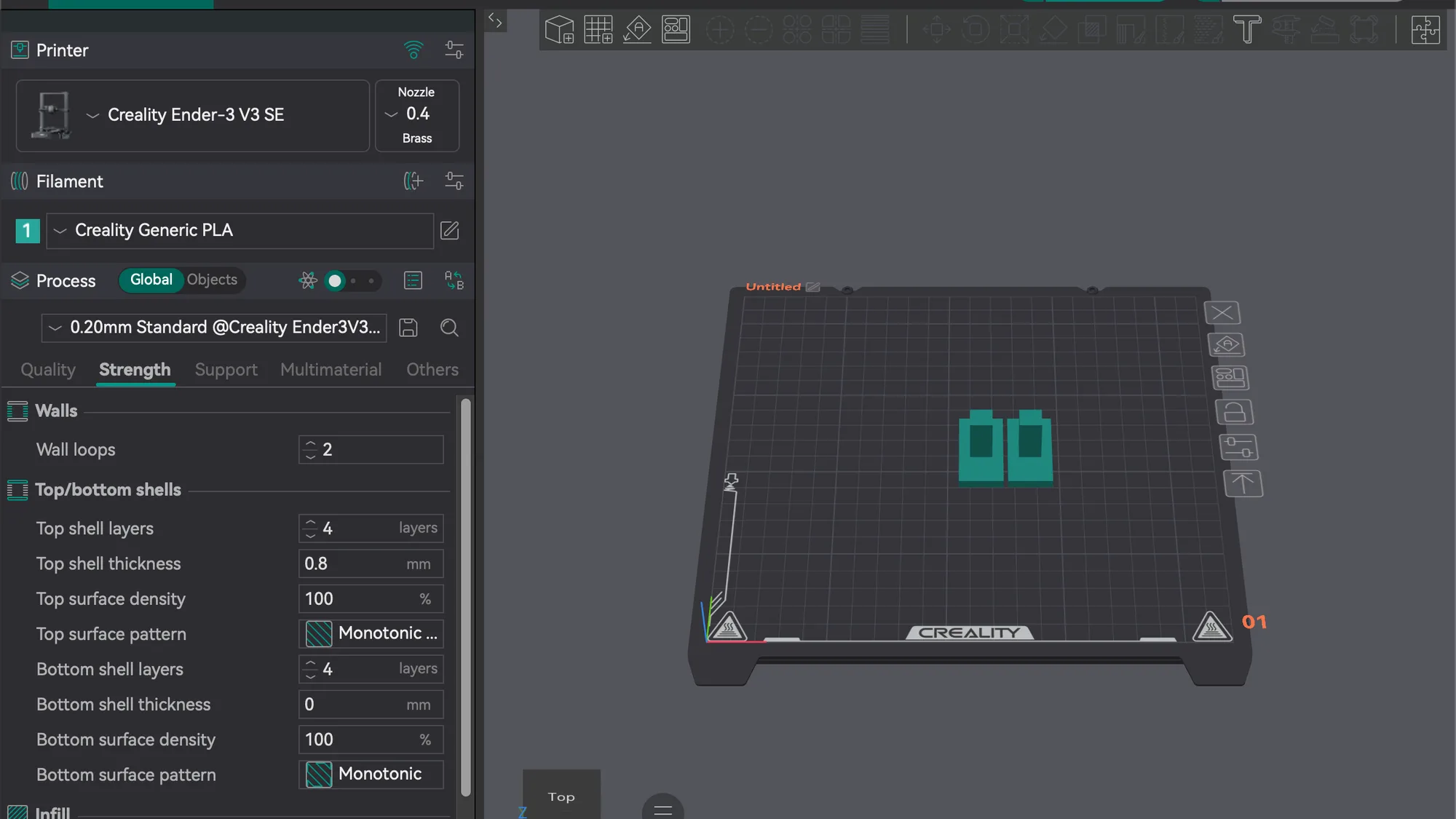
Start on the Prepare tab with a model on the plate. We used the same two overhang-t parts as before, with the Creality Ender-3 V3 SE printer, Creality Generic PLA filament and the 0.20mm Standard Process preset, in Simple mode. If you have not met the Process panel yet, the Quality tab lesson comes first.
In the left panel, under the preset drop-down, click Strength, the second of the five tabs. In Simple mode it shows these fields, top to bottom:
- Walls: Wall loops.
- Top/bottom shells: Top shell layers, Top shell thickness, Top surface density, Top surface pattern, Bottom shell layers, Bottom shell thickness, Bottom surface density, Bottom surface pattern.
- Infill: Sparse infill density, Fill Multiline, Sparse infill pattern, Internal solid infill pattern.
The panel scrolls, so the Infill group sits below the fold at first. Drag the scroll bar at the right edge of the panel, or scroll with the pointer over it. We did not switch to Advanced or Expert mode, so we cannot say what extra Walls fields appear there. The walls and perimeters guide covers the ideas behind them.
What do Wall loops and the shell layers mean?
Hover the pointer over a field for about two seconds and OrcaSlicer shows its tooltip. We read three of them:
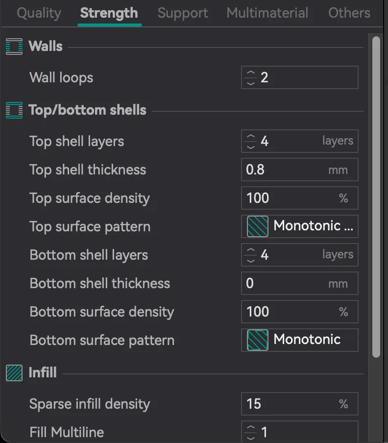
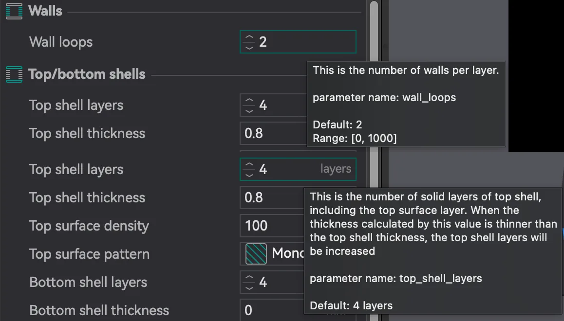
- Wall loops: "This is the number of walls per layer." Setting name
wall_loops, default 2, range 0 to 1000. - Top shell layers: "This is the number of solid layers of top shell, including the top surface layer. When the thickness calculated by this value is thinner than the top shell thickness, the top shell layers will be increased." Setting name
top_shell_layers, default 4 layers. - Bottom shell layers: the same wording for the bottom shell. Setting name
bottom_shell_layers, default 4 layers.
The tooltip for Top shell layers explains the neighbouring field too. Top shell thickness read 0.8 mm in our preset. At 0.20 mm layers, 4 layers is also 0.8 mm, so the two agree and neither overrides the other. With a finer layer height, the thickness field could raise the layer count, which is what the tooltip says. We did not test that case. Bottom shell thickness read 0, so only the layer count applies there.
How do you set sparse infill density and pattern?
Scroll to the Infill group. Sparse infill density read 15 with a percent sign. Its tooltip: "Density of internal sparse infill, 100% turns all sparse infill into solid infill and internal solid infill pattern will be used." Setting name sparse_infill_density, default 15%, range 0% to 100%. To change it, click the field, select the contents with Cmd+A, type a number and press Tab.
Next, Sparse infill pattern read Cross Hatch in this preset. Its tooltip is short: "This is the line pattern for internal sparse infill." Setting name sparse_infill_pattern. Click it and a list opens with an icon beside each name. We scrolled the whole list and counted 26 patterns:
Rectilinear, Aligned Rectilinear, Zig Zag, Cross Zag, Locked Zag, Line, Grid, Triangles, Tri-hexagon, Cubic, Adaptive Cubic, Quarter Cubic, Support Cubic, Lightning, Honeycomb, 3D Honeycomb, Lateral Honeycomb, Lateral Lattice, Cross Hatch, TPMS-D, TPMS-FK, Gyroid, Concentric, Hilbert Curve, Archimedean Chords and Octagram Spiral.
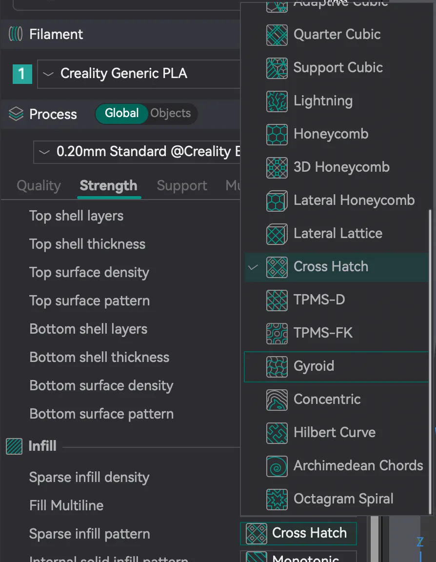
We picked Gyroid to try a second pattern. Three things changed on screen: the Sparse infill pattern label turned orange with a reset arrow beside it, the preset name and the Strength tab name turned orange too, and a new row, Z-buckling bias optimization (experimental), appeared under the pattern, unticked. We left it unticked and did not read its tooltip. Clicking the reset arrow brought Cross Hatch back. For the general idea of what infill does, see infill explained.
How do these settings change the slicer estimate?
We sliced the same plate five times, changing one setting each time from the defaults, and read the Total estimation box on the Preview tab. Layer count stayed at 120 (the top number on the vertical slider) in every run. The filament was Creality Generic PLA. Everything below is the slicer's own estimate and nothing was printed.
| Setting changed | Walls / top and bottom / infill | Estimated total time | Estimated filament |
|---|---|---|---|
| None (defaults) | 2 / 4 and 4 / 15% Cross Hatch | 27m15s | 6.70 g (2.25 m) |
| Wall loops 4 | 4 / 4 and 4 / 15% Cross Hatch | 29m11s | 8.16 g (2.74 m) |
| Sparse infill density 40 | 2 / 4 and 4 / 40% Cross Hatch | 30m2s | 8.54 g (2.86 m) |
| Top and bottom shell layers 6 | 2 / 6 and 6 / 15% Cross Hatch | 29m1s | 7.84 g (2.63 m) |
| Pattern Gyroid | 2 / 4 and 4 / 15% Gyroid | 27m15s | 6.68 g (2.24 m) |
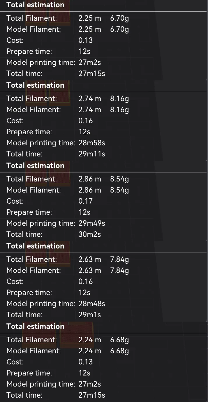
Reading the table: raising wall loops from 2 to 4 added about 7 percent to the estimated time and about 22 percent to the filament. Raising density from 15 to 40 percent added about 10 percent to the time and about 27 percent to the filament. Six top and bottom layers instead of four added about 7 percent to the time and about 17 percent to the filament. The Line Type table beside the estimate shows where it went: at 2 wall loops the Inner wall row read 4m47s and 1.15 g, at 4 loops it read 10m8s and 3.21 g, and at 40 percent density the Sparse infill row went from 5m18s and 1.40 g to 9m53s and 3.25 g.
Gyroid at 15 percent matched Cross Hatch on time and was a hair lighter on filament. One plate and one density is not enough to rank patterns, so treat that as a single data point. The next lesson, orca-slicer-speed-and-advanced-mode, covers speed and the other modes. The print speed vs quality guide is a good general read in the meantime.
Next lesson: Orca Slicer Advanced Mode: Unlock Speed and More Settings.